![]()
Reassembly
I have decided to start a new page for the reassembly, because I think there'll be quite a lot to say if the first small steps are anything to go by!
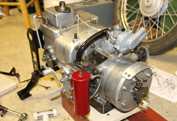
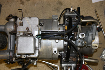
First of all, I made a rough wooden stand for the engine, approximately the height the engine would be if the bike was on the centre stand. I ceremoniously plonked the engine on this stand and re-attached the oil filter and its associated piping, the carburetter and the gearchange with linkage.
In fact the carb was the first problem. I had dismantled it some time ago and discovered that the fuel inlet banjo is the wrong one and doesn't fit very well. A bit of adjustment with the grinder has it fitting OK but then I discovered that the needle valve is still off its seat when the float hits the top of the float chamber. This is a bit of a mystery and makes me wonder if the needle valve assembly is the correct one for this carb. Anyway, for now I've packed the top of the float with a thin aluminium shim and it all works satisfactorily - at least in that the needle shuts before the float runs out of travel. If this doesn't prove satisfactory I'll have to try to find some new carburetter parts. This is a good example of how a 5 minute job can take 2 hours!
I wish I'd taken a photo of the gear pedal and linkage before I dismantled it! It's amazing how long it can take to get 3 parts all the right way round so that they all link up correctly! Another learning point here.
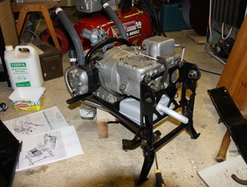
Reassembly starts around the engine |
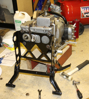
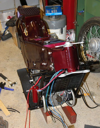
Rear view of the engine and gearbox ready for reassembly |
|---|---|
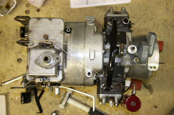
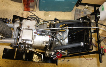
Looking down on the engine and gearbox |
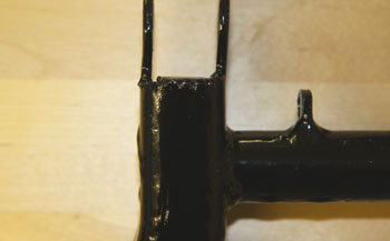
On the LE Velo, the centre stand is odd in that it doesn't quite reach the ground! This means that the bike leans one way or the other, resting on juat one of the two feet of the stand. The reason is historic - earlier models had a hand starting lever, which also retracted the stand automatically. A bit of a defect with the design of the stand is that the stand wears away at the point where it bears on the rear "cross-member" - the plate on the back of the engine. Mine had worn to the point where it would flip up forwards or backwards, but wouldn't remain in the down position. Not a lot of use! I welded two small reinforcing pads onto the stand to fix this, but in the meantime, I was offered a new stand which had been modified to place both feet on the ground, this was freshly powder coated and looked a lot better than mine. However - when I came to fit this new stand, I found the pivot holes are badly worn and it has the same wear problem as mind had. So, I resurrected my stand and it has now got a coat of primer and I'll finish it with Hammerite in the next few days. The picture above shows the new stand with modified feet, partly assembled.
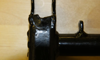
The original stand is now painted and fitted. The following pictures show the worn area mentioned above:
The "new" stand showing the wear which allows it to flip forwards as well as back |
The same view of my original stand with a piece welded in to correct for the wear. |
|---|
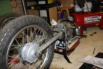
My next task was to re-attach the back wheel, swinging arm and driveshaft. This was just a few minutes work and I moved on to the front cross-member and the bottom part of the radiator frame. None of this seemed to line up very well and on examination I found that both these parts were slightly bent backwards, probably the bike has run into something on both front corners. It can't have been a very hard impact because I could quite easily straighten these parts wth a vice and molegrips! After that, it fitted together fine and I also fitted the exhausts and silencer.
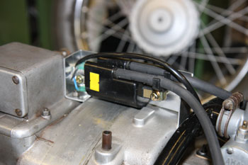
Since I will not be re-using the original ignition colis, which are well past their best, I now had to find a place to mount the new dual-ended coil I got from Paul Goff (http://www.norbsa02.freeuk.com/goffylighting.htm) I used aluminium to make up a bracket and this is now primed and waiting for a coat of paint.
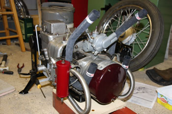
Front view of engine with exhausts fitted and radiator hoses just put in place. |
Rear view of engine showing silencer, brake pedal and stand in place. |
|---|---|
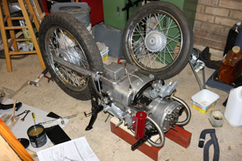
General view showing rear wheel, etc re-attached, also kick-start pedal |
Swing arm and driveshaft viewed from rear. |
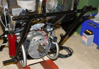
New ignition coil and bracket in place. |
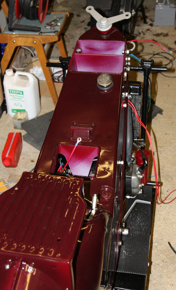
Top view showing position of coil above bell housing. |
Petrol tank etc.
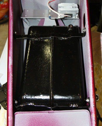
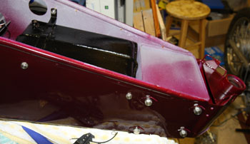
The next task was to re-fit the petrol tank in the body. This looked like a 5 minute job - turn the body over, plonk the tank in place and insert 4 bolts. The first issue was that the mounting brackets were somewhat bent - I didn't remember this happening, but I assumed it was my fault and straightened them out nicely. Mistake! none of the holes lined up until I had re-bent them. As you'll see from the photo below, the tank isn't central in the body, it lies off to one side and it looks as if the brackets are "adjusted" to make it fit. I had bought a new rubber grommet for round the filler neck, but of course when you try to fit the tank it pushes the grommet out again. I'll have another go at that now the tank's in place.
Next problem with this is that with the tank in place, you can't fit the steering head - or vice-versa. You have to get both items more or less in place, then start inserting bolts. If I had to do this again, it would be a 5 minute job!
I had previously got a set of stainless steel bolts for the tank and steering head from SiLEnt Stainless - not cheap, but it does do a lot for the appearance!
This picture shows the tank in place - it sits off to one side for some reason, maybe to bring the petrol tap closer to the access hole in the side of the body |
Another view of the tank and steering head in place - note my nice stainless steel bolts from Silent Stainless |
|---|
The next step was to put the top and bottom yokes in place. There are 20 balls in each race and they were easily held in place with a spot of grease in the usual way. The bottom yoke has the tube attached and is simply inserted from the bottom, the top bearing cone isn't threaded and just slips over the top of the tube, followed by a dust cap and a nut. This is a shouldered nut and the shoulder is a tight fit inside the top yoke. I'd painted this and I had to scrape the paint off from inside the hole! Finally, the domed top nut goes on top of the top yoke. It turns nice and smoothly and I don't think I'll have any trouble there.
I still have a residual problem with the petrol tank though. The filler neck is tight up against the front edge of the hole in the body. Not sure why, but I'll have to investigate that.
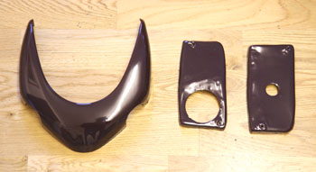
NOW, a bit of a milestone - I managed to finish off painting the last 3 parts which had got missed earlier. The weather has turned very cold, but today it was at least dry and sunny, so I put a fan heater on in the shed for a couple of hours and then did my bit of spraying. It was nice and warm in there and it went well.
Top and bottom yokes back in place (viewed with body lying on its side!) |
Headlamp cowl and legshield tops - the last items to be painted. |
|---|
Rear Suspension
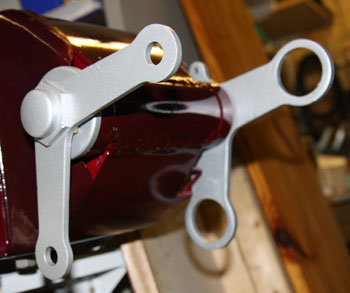
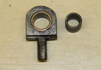
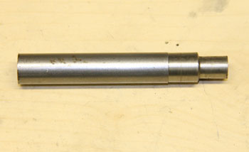
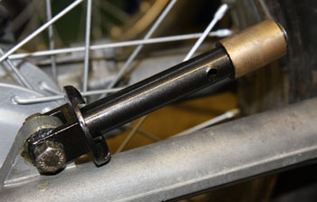
The rear suspension is very simple and is not a great design. It consists of two coil springs around what looks like a telescopic damper - but isn't! The inner part is just two sliding tubes.The bottom of the unit pivots on a lug on top of the swinging arm and at the top there is an eyebolt. Each pivot consists of a steel bush running inside a phosphor bronze bush. In my case all 4 pivots were seized solid due to the steel bush rusting. There is nothing to prevent the ingress of muck and water. Every LE owner needs to make a drift to knock out the bushes, as shown here:
Eyebolt and bush |
Bush removal tool |
|---|
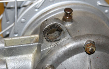
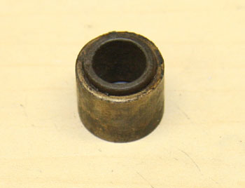
The first 3 bushes came out OK, though I was a bit horrified at how hard I had to hammer the drift! I then cleaned off the rust with fine emery and re-assembled it. The 4th bush also came out, but it brought the phosphor bronze bush out with it. I then had a bit of a game getting the two bushes apart, after which I cleaned the bush and its hole with thinners and loctited it back in place. Finally I got it all assembled with all the pivots moving smoothly and freely. I guess these will need regular maintenance.
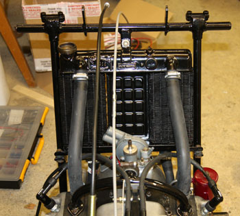
After this, I re-fitted the radiator frame and radiator, and put back the 4 hoses. I had to get new Jubilee clips for the hoses and was pleased that my local hardware shop stocks genuine Jubilee clips in all sizes and had plenty in stock! You need 8!
The phosphor bronze bush came out on this side |
The steel bush stuck inside the phosphor bronze one. |
|---|---|
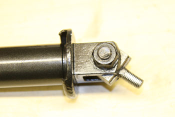
Eye bolt reassembled |
Lower suspension tube back in place |
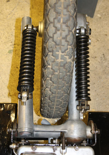
Both suspension units back in |
Top view of reassembly coming on |
Radiator frame back in place |
Radiator back in |
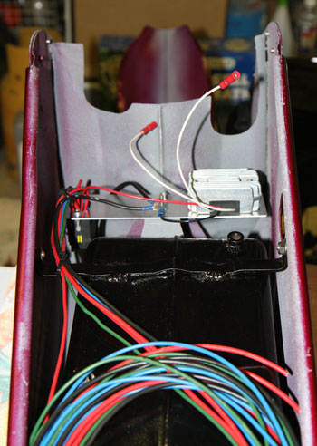 |
I also completed most of the wiring which connects to components inside the body. The large coil of wire goes mainly to the headlamp.
The front forks
Once again I make the mistake of thinking something is going to be a 5 minute job! Well, how hard can it be to shove the suspension units up through the various components and stick a nut on top? So, referring to the diagram on Page 41 of the parts book I made a start. Well after about 10 minutes study and looking at the parts involved, I realised that in the illustration, the forks are viewed from the rear, while the headlamp cowl assembly is viewed from the front! This is quite confusing because you have to mentally reverse the position of all the asymmetrical bits, of which there are plenty! Next you can easily see that several parts are missing from the diagram, which means you have nothing to show you the order of assembly after a great deal of trial and error, and much tearing of hair, I eventually discovered that there is an error on the diagram - items 34 and 35, the two small brackets which support the top part of the headlamp cowl are shown upside down and back to front. The correct order then, starting from the bottom is:
1. Front mudguard stiffening plate
2. Front mudguard
3. Bottom Yoke
3(a) Right hand fork only, brake cable guide.
4. Lower headlamp bracket fixing bracket (item 32/33)
5. Fork lock-ring
Then, on top of the upper part of the front fork:
1. Top Yoke
2. Handlebar bracket
3. Upper headlamp bracket fixing bracket (item 34/35). Note the threaded part of this points forward and down, not backwards and up as illustrated!
4. Washer and nut.
Notes:
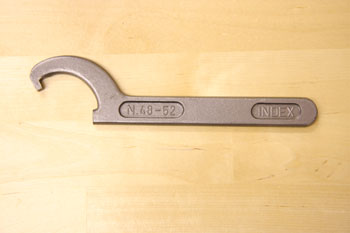
You'll find you need a good strong lock-ring spanner, fortunately I have one - inevitably it came from an auto-jumble, but I'm told there are other places to buy tools.
Some illustrations of all this:
Top part of forks assembled - note the brake cable guide is not visible in this view |
Top headlamp bracket fixing |
|---|---|
Front forks, etc in place |
This is the calibre of lock-ring spanner you'll need - the pressed steel ones are just not up to it |
Footboards
I re-fitted the right hand footboard a week or two ago and had a small struggle with the holes in the support bracket not wanting to line up with the holes in the footboard. After a bit of fiddling I managed to assemble it and thought no more about it. The new footboard looked so much better than the old one, I decided to get another new one from Bullers End. This arrived last week and I've now painted it (they come unpainted).I simply couldn't fit this one at all and on examination I found that the underside of the new footboard fouls the bracket just enough to stop the holes lining up. Rather than taking it all apart again, I decided to elongate the holes - if I'd known earlier, I would have filed a bit off the brackets.
Putting the body back on
After a bit of study, I decided to remove the front forks, front mudguard, etc again (yet again!) to make it easier to put the body back on. It was also a lot easier to handle like that. Reassembly is actually pretty straightforward - I placed a board across the top of the gearbox to take the weight of the body while I was lining everything up. I also had to connect various bits of wiring underneath the body - much easier with it supported on a board. In fact there is very little clearance between the bottom of the battery box and the top of the gearbox, so I had to move the position of the regulator - not a serious setback!
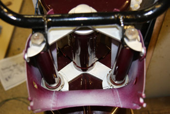
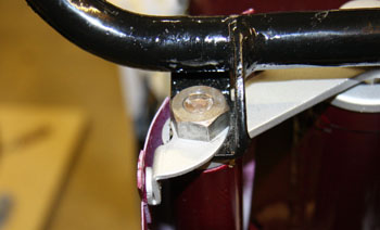
Once the wiring was sorted out, the two brackets on the top of the radiator frame have to be guided into place and at the same time, the rear suspension units have to be located in the curved slots - fiddly but straightforward. Finally, the two bolts can be inserted in each of the "mutton chops", through the swinging arm pivots and into the curved and threaded brackets.
I found it too difficult to guide the throttle, clutch and speedo cables into place at the same time, but it was quite easy to do it after the body was in place.
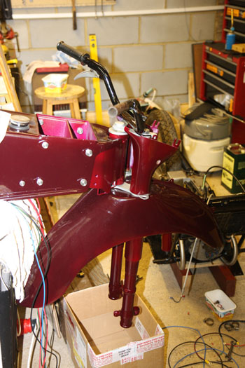
Next job was to re-assemble the front forks, mudguard and so on - as outlined previously. It only took a few minutes this time! See comments under Electrical for re-wiring the headlamp shell.
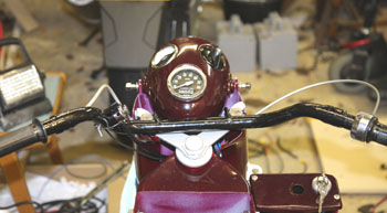
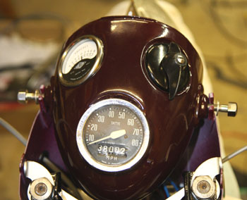
The instruments were re-fitted to the headlamp shell and the handlbars re-fitted with the clutch lever, throttle and dipswitch/horn button. I also re-fitted the right hand legshield, ready for wiring the horn and the new ignition switch. By the way, I think the fluorescent lights in the garage tend to fight with the camera flash, resulting in some inconsistent colour rendering at some angles!
Body mounted on the frame again, cables threaded through the steering head guide |
Rear view of the body re-mounted |
|---|---|
Handlebars re-fitted with clutch lever, throttle and horn/dipswitch |
Headlamp shell back in place and instruments fitted |
The front wheel saga
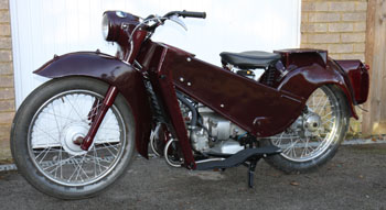
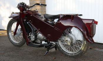
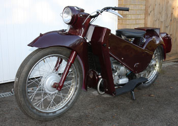
Well I finally got the rest of the bike assembled and wheeled it out into the winter sun to take a few photos:
 |
 |
|---|---|
 |
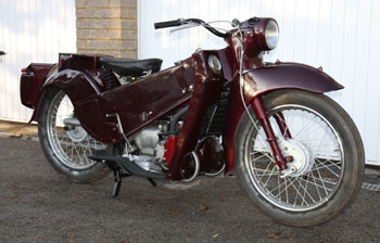 |
There is a problem however! The front tyre almost contacts the right hand fork leg, much too close for comfort, and when I dismantled it, there was a thick washer between the brake plate and the right fork. This washer shouldn't be there. After much checking and measuring, I have found that the wheel has been built with the wrong offset, so that when assembled, the wheel end up about 8mm too far to the right. That 8mm is what should be the clearance between the tyre and the fork. The thick washer had obviously been added at some time to try to compensate, but it doesn't really work.
So, the wheel has just gone off to a wheel builder to be corrected. In the meantime, I have ordered a new tyre, tube and rim tape.
By the way, the wheel builder was just assembling some nice new wheels with stainless steel rims and spokes, they looked wonderful so I asked the price - I wish I hadn't! The rims are £100 to £120, the set of spokes is also over £100 (per wheel!) - plus his labour. I think I can live with a bit of pitting in my chrome.
More on the front wheel
The news from the wheel builder isn't good. The nipples are rusted onto the spokes and despite copious use of WD40, the spokes are breaking as he tries to undo them. This means a new set of spokes and a wheel re-build. Another £80 away! I should have it next week.
Collected the front wheel rim and hub from the wheel builder, wire brushed and 1st coat of paint applied to the hub and the inside of the rim. May as well tidy up these details while I have the chance. After discussion with the wheel builder, it was either £86 with plain non-butted galvanised spokes, or £109 with butted stainless steel spokes. Decided to go for the latter.
The front wheel was finally re-fitted with a new tyre and tube. I decided to go for the Czech-made Mitas tyres, seem to be good quality and are dead cheap at about £24 each!
Going for the MOT
After some months of no activity on this project, I eventually got around to finishing things off in July. New rear tyre fitted and an MOT booked for 22nd July. The ride over to the MOT station was great, though it did expose a couple of issues as expected.
The feet of the centre stand touch down far too easily on the road when cornering - I'll have to look into that, though I'm not sure what can be done! The bike seems to have a top speed of around 45 to 50 on a flat road and I have a slight feeling that the ignition isn't advanced quite enough at this rpm. I'll give a bit more attention to the timing, etc.
The carb still isn't right. Despite a new float needle and various other bits, it is still tending to glood from time to time, as well as occasionally drying up! It looks as if the float needle has a tendency to stick.
The good news is that the brakes are much improved by re-shimming and a bit of bedding in.
Updated: 23rd July 2011