![]()
Electrical system
Charging and Lighting
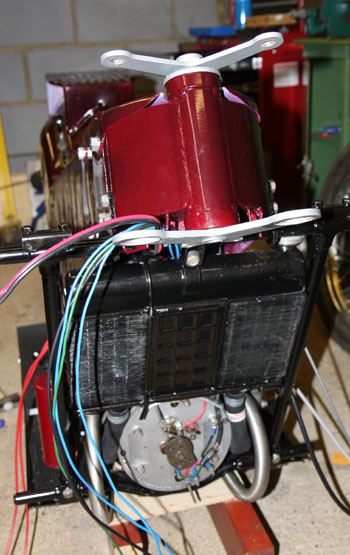
The LE Velocette has a very simple electrical system, using components produced by Miller of Birmingham. As originally conceived, simplicity was a virtue. The system is 6 volt, positive earth, using a 42 watt single-phase alternator with a selenium rectifier and no form of regulator. The heart of the system was a 6-position switch, controlling ignition and lighting. There was no brake light and the headlamp had two bulbs - a "pilot" bulb, the equivalent of "sidelights" and a headlamp bulb. The printing is unclear on my wiring diagram, but the headlamp was probably 24 watts and the pilot, around 5 watts. I think it says 3W for the rearlamp.
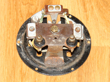
The 6-position switch connects different combinations of the 3 alternator coils according to the load - i.e. one coil only for ignition only, two coils for ignition plus pilot light and 3 coils for ignition plus headlamp. This should generally work OK, but creates opportunities for over-charging as well as for flat batteries. There is also an "emergency ignition" position where one coil is connected directly to the ignition, by-passing rectifier and battery. This requires the flywheel to be accurately positioned on the crankshaft so that the voltage pulse from that one coil happens when the points are closed - and is still there when they open. That is the only engineering reason for positioning the flywheel correctly relative to the crank. However, since the flywheel has a timing mark (in the form of a hole) used for setting the ignition timing, it is still a good idea to position the flywheel correctly.
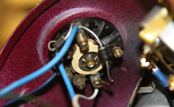
View of the 3 alternator coils |
The 6-position Miller switch |
|---|
The Miller 6-position switch is in poor condition and will need to be replaced or repaired whatever I do.
All this is a bit of a worry because driving on today's roads demands a better standard of lighting than this. When you consider that a modern motorbike has a 12v 60W halogen headlamp (and maybe two of them!) backed up by an alternator of 300W or more, you can see that a 24W headlamp is going to be pretty dim.
This is made worse by the fact that the components are not really up to today's standards of quality or weather-resistance. The Miller switch in particular is not really suitable for a motorbike, having no protection from damp. This is a 6 volt system, where contact resistance is critically important - needing to be twice as good as on a 12v system. Of course all this is made to the standards of the day (50 years ago) and I don't intend these comments to be critical - however times have changed!
My plan is as follows:
Ignition system
The existing system uses two HT coils connected in parallel and also in series with a ballast resistor. There is one set of points and both coils fire every revolution.
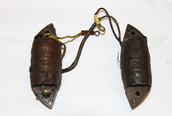
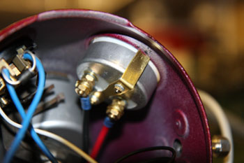
The original HT coils |
The original points, showing the cam lubricator and the hole where the capacitor goes |
|---|
These components are located on the front of the engine, protected by an aluminium cover with no seal. Again, scant protection from the elements for components made to the standards of the 1950s. The Miller points don't have a built-in pivot pin, so this is not replaced when you replace the points. The pivot pin is fixed to the stator plate, and in my case was rusty and seized. The points though were in good condition and should be fine after cleaning and lubricating the pivot and polishing up the actual contacts.
Unfortunately, one of the HT coils is open circuit. I did some tests on the good coil and it produces a pretty weak spark. Maybe it's got some shorted turns or maybe it's never been too great, I'll never know! I plan to replace the coils with a dual-output coil from Paul Goff (http://www.norbsa02.freeuk.com/). The original capacitor tests OK, so I'll use that and the Miller points, so the ignition system will have some authentic components at least! If I can fit the new coil unit invisibly under the cover on the stator plate, I will.
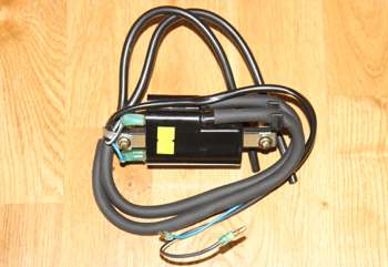
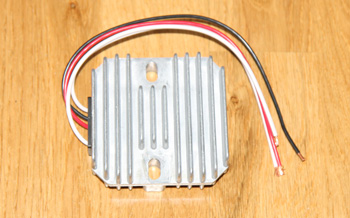
New twin-output coil and 6 volt solid-state regulator ordered and quickly received:
New twin-output ignition coil |
New solid-state regulator |
|---|
Note that the coil is too big to fit on the stator plate under the cover, unfortunately but I have some other ideas!
The Horn
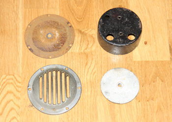
The horn is in place and original, but it doesn't look good and it doesn't work! It is marked "Clear Hooters Ltd. B'ham England" and is model HF-140. Some photos after dismantling:
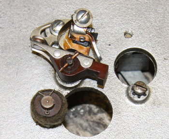
The horn mechanism - "buzzer" |
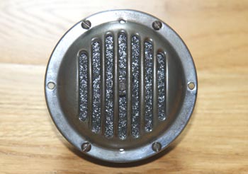
Horn parts - diaphragm, rear casing, front grille, diaphragm weight |
|---|
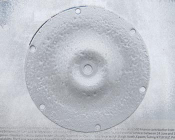
After cleaning the contacts, removing various dead insects, etc. the mechanism buzzes with the diaphragm removed, so it can be made to work. I will give it all a good clean, give the diaphragm a coat of paint and also re-paint the casing. I think the grille will clean up OK.
Sorting out the horn was a comparatively easy task, working with small parts which you can hold in your hand! The horn works well and is surprisingly loud!
Horn diaphragm after re-painting |
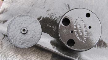
Diaphragm weight and horn casing after painting |
|---|---|
Horn re-assembled |
Re-wiring
I've made a start on the task of re-wiring, by putting in connections for the alternator and the ignition, just the wiring to the stator plate so far.
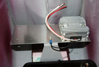
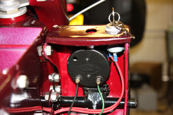
I also made a bracket for mounting the regulator and fuses either side of the battery (see below) - more on this later. I have been to Paul Goff's website once again and got an LED insert for the rearlight. This is another power-saving idea - I'm a bit concerned with having a 42 Watt alternator, being used to 400 Watts on modern motorbikes!
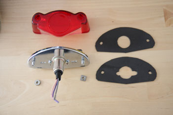
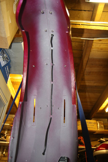
I had a bit of fun and games making a gasket to fit behind the rearlight. All I could get on a Sunday was something called "Fab Foam" from an art shop, I had to use two layers. After posting a question on the LE Velo forum, I am told that the wiring for the rearlight was routed along the top of the rear mudguard on early Mk IIIs, and later it passed under the mudguard via two grommeted holes and held by a number of metal tabs. Well my bike has the tabs, but not the holes, so I decided to drill holes and make use of the tabs.
Mounting bracket for regulator and fusebox under battery |
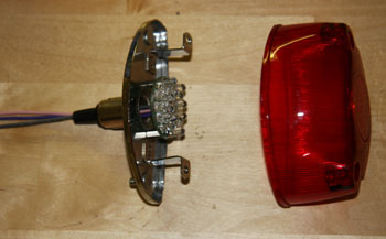
LED insert fitted in rearlamp |
|---|---|
|
LED rearlamp - kit includes a grommet for the cables |
Some home-made rubber gaskets for the rearlamp |
The rearlamp wiring is routed along the mudguard..... |
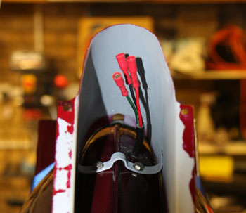
.....and out through a hole under the numberplate bracket. |
Having now installed most of the wiring, I decided it was time to draw a wiring diagram, especially as I've started to forget which colours I've used for which purpose. I've found an ancient copy of Visio which I might try to install to do a neat diagram.
Re-wiring the body and headlamp shell
I designed the wiring so that it can all be disconnected on bullet connectors either under the body or in the headlamp shell. So, when re-mounting the body, I supported it temporarily on a board laid across the top of the gearbox while I connected the bullets. I could then lower the body into place, taking care not to trap the brake light wiring. I was then able to complete the mounting of the body. A also re-fitted the right hand leg shield, containing the horn and the new ignition switch (not an original fitting).
I fitted the instruments into the headlamp shell, including the new "Miller style" ammeter, which has such a flimsy mounting bracket, I had to put a bend in each leg to stiffen them and stop them just slipping (see photo). Re-mounted the headlamp shell and pulled all the wiring in through the hole in the underside. It was now a simple job of connecting up all the wiring. Note:
Wiring for new ignition switch and horn - before tying in. |
Front view of body showing wiring ready for headlamp shell fixing |
|---|---|
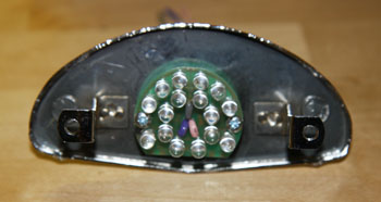
Headlamp switch, showing diodes feeding rearlamp |
New pattern ammeter, showing bend in mounting bracket to stiffen it. |
After completing connecting up the wiring, the fuses were inserted and I did a resistance and insulation test on every circuit. Next was to connect the battery and check that everything works. All looks good!
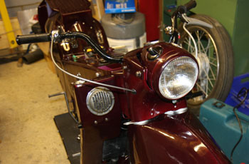
Up to this point, the headlamp shell is fine, however, the reflector was badly corroded and dull, and the rim was damaged as well as pitted. I have been trying to find a new rim without success, so I have straightened the old one as best I can and just painted it. I also got a new reflector and glass from Paul Goff. Several problems! I didn't do a great job of painting the rim, so I'll have to re-do that at some point. In fact I don't think I seriously expected to be using it, so I don't think I took as much care as I should have done with the spray gun. Secondly, the new reflector is fractionally bigger than the original, so it's a tight fit inside the rim. Finally, the lug for the clamp bolt is missing, so I'll have to improvise. Well, eventually it is re-assembled and it works fine:
Headlamp re-fitted - makes the bike look almost complete |
Headlamp cowl re-fitted |
|---|
I still haven't fitted the two lower fixing bolts in the lower part of the cowl because I can't get the holes to line up. Well, you wouldn't want it too easy would you? Well, yes I would actually!
Updated: 29th November 2010