![]()
Engine re-build
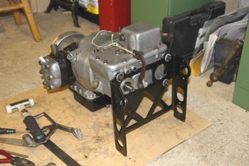
The engine was stripped, apart from the crankshaft and bearings. This was because of the need for special tools which I don't have. The bearings were checked carefully for play and seem to be OK. All parts were cleaned and re-assembled with clean oil, all oil pipes were removed and flushed through with de-greaser and then oiled with a pump-action oilcan.
The exterior of the engine was very dirty with old oily muck and was also partly covered with over-spray from a previous re-spray. Additionally, some kind of varnish had been applied to the joint between the crankcase and the bellhousing - presumably in an attempt to cure an oil leak. This meant that after cleaning the oil off with paraffin, all the cases had to be cleaned with wire wool to remove varnish, etc. This meant careful masking to prevent fragments of wire wool ending up inside oil-ways, etc. Rather a tedious job, but it's nice to see it all coming clean and bright again!
Internally, the engine was full of old oily sludge - this was fairly easy to clean off, though it's a very messy job.
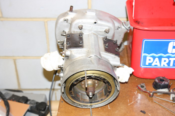
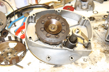
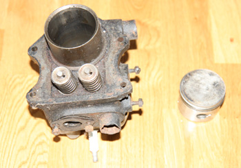
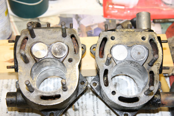
Engine casing after cleaning |
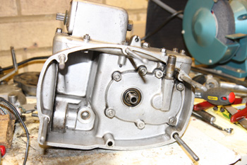
Gearbox (clutch side) after cleaning |
|---|---|
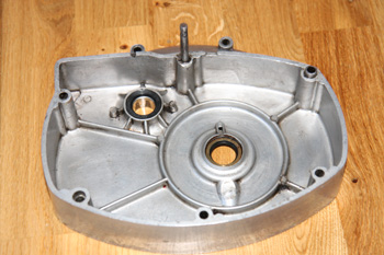
Clutch housing after cleaning |
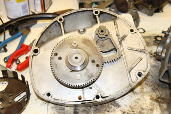
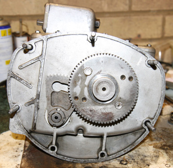
Reduction gear and starter segment re-fitted - NOTE segment is upside down! |
Clutch and starter shaft re-fitted |
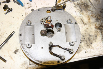
Stator plate (top) after cleaning. Points temporarily re-fitted |
Stator plate bottom view showing alternator coils. |
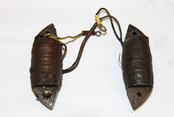
HT coils before re-fitting to stator plate. I may replace these with a modern equivalent. |
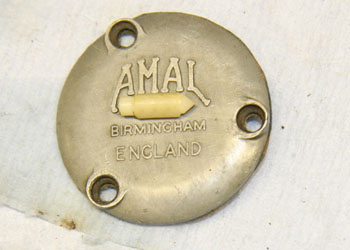
As can be seen above, I also stripped and cleaned the stator plate which was very dirty. The points were seized on their pivot, but actually in good condition. A quick clean with 6x0 grade emery and they are fine. The alternator has 3 coils and 3 magnets - i.e. 3 N poles and 3 S poles. I intend to parallel the 3 coils and fit a regulator. The original system relies on coil switching via a 6-position switch which is in very poor condition. I hope to fit a re-manufactured 3-position light switch, which has a similar appearance to the original. I'll also fit a separate ignition switch and some fuses.
On testing, one of the HT coils is open-circuit so will need to be replaced. The capacitor tests OK, surprisingly!
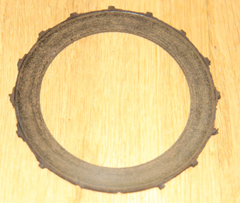
When I first came to re-assemble the clutch, I found the driving "ears" on the friction plates were very worn - in fact worn away in some cases. This necessitated obtaining new friction plates.
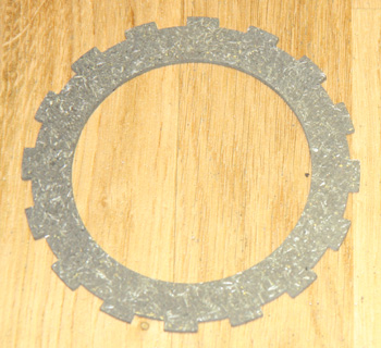
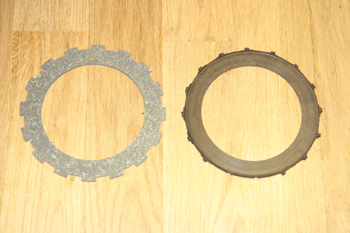
The old clutch plates were badly worn, in fact the ears are practically worn away..... |
....when compared to a new plate. |
|---|---|
Side by side they look even worse. |
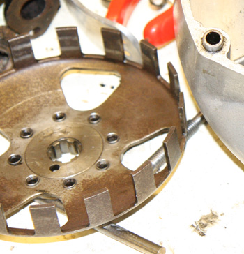
The clutch basket shows signs of the plates slipping but fortunately the teeth aren't worn. |
On close examination, it is clear that the old plates have at some time stuck to the metal plates and it was necessary to scrape bits of clutch lining off the metal plates and then rub them smooth.
With the new plates available, it was then a simple matter of re-assembling the clutch. I found it useful to use the clutch basket to help align the plates during assembly. It is possible to fit 4 of the 8 nuts through the holes in the basket, thus ensuring that the teeth on the basket will slip into place easily afterwards.
Re-assembled the bell housing to the gearbox. This needs some patience as the following have to happen simultaneously:
This last one is tricky because the kick-start shaft tends to move when you aren't looking and the lever on the starter shaft then slips in underneath it - i.e. out of engagement. Colourful language may ensue! Of course all the above is happening inside the casing and therefore out of sight.
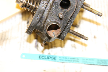
Note that when this is assembled, the reduction gear, etc will be pushed towards the engine side and will bind on the casing until it is engaged with the engineAnother opportunity for panic when it won't turn easily! One last point here, the starter segment needs to be on the right way round. OK that sounds elementary, but it will go on the wrong way round and it even lines up more or less. In the photo above, it is on the WRONG way round! The picture below is correct.
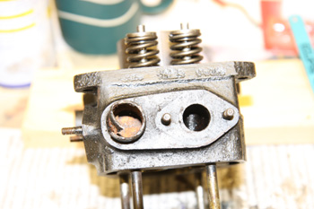
Turning to the engine, I had already stripped and cleaned the oil pump and removed all the oil pipes for cleaning. I had to make new aluminium washers for some of the oil fittings, but re-assembly was straightforwards. I re-fitted the sump with a new gasket to keep everything clean.
I now removed all the valves and re-ground them, no problems here. I have an old valve spring compressor, marked "Morris" which was perfect - it's never fitted anything else I've worked on!
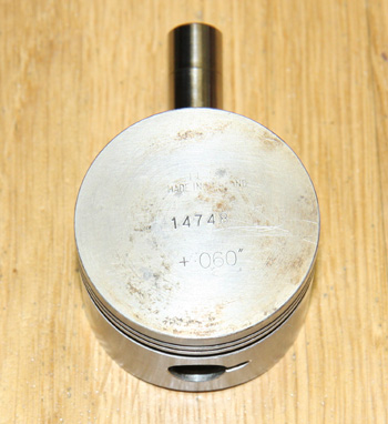
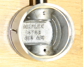
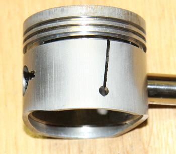
I now re-fitted the left-hand cylinder and head. No problem there. Turning to the right cylinder, I saw that the middle (compression) ring was broken. Curses! I should have spotted that sooner. Some photos of the piston follow:
The piston is marked +0.060" oversize, but looks as if it has seen very little use. |
The markings inside the piston |
|---|---|
The split in the side of the piston identifies this as an early-type piston. |
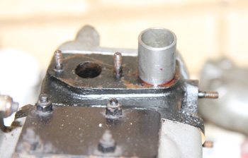
View showing starter segment correctly aligned |
I now contacted Alf Snell, an engineering expert who does a lot of work for the LE Velocette club members and he confirmed that these are early-style pistons which, among other issues, have very shallow ring grooves (0.070"). Modern piston rings are too deep for them. This means either machining the grooves deeper or resorting to second-hand rings. Modern rings only go up to +0.040", and although they would work, the ring gap would be wider than intended. Also, it would be quite tricky to machine the grooves deeper on an amateur lathe. Alf kindly offered to send me a "handful" of serviceable second hand rings, so I've settled for that. This should get me going and I may try to organise new barrels and pistons later.
This is not going well! Alf kindly sent me about a dozen assorted piston rings, but there are two big problems with them. Firstly, they are a later type and the rings are too deep for the grooves. The older rings are about 0.065" deep (groove depth 0.070") and the new ones are about 0.096" with a groove depth of about 0.10". This is a show-stopper anyway, as I don't think I could machine the grooves deeper very easily on a normal amateur lathe. However, I'd give it a try if it weren't for the second problem. My barrels are bored to +0.060" and I think all these rings are for standard bores. This means not only an excessive ring gap, but the compressed radius of the ring is also wrong, meaning that the ends of the ring tend to lose contact with the cylinder wall. These rings are unuseable with this piston.
So, my new plan is to get up to Bullers End next week and see if I can sort out two good barrels for Alf to re-bore and fit new pistons. This is unwelcome extra expense, but I don't see a sensible alternative.
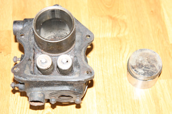
At Bullers End I was lucky enough to get two very good barrels at +0.020", complete with valves, pistons and heads. However, I spent a good hour getting the head off the left barrel, which had rusted to one of the studs. Not a great problem though, because although I've made some scratches on the head, the barrel is fine and I can use one of my old heads. The other head came off easily. The new parts:
Left cylinder |
Right cylinder |
|---|
I checked the wear on the left barrel as follows:
I inserted a piston ring at the very bottom of the barrel, i.e. in the un-swept area and squared it up with the piston. Ring gap measured at 0.006". Moved the ring to various places in the swept area and measured a maximum ring gap of 0.012". Now for a bit of maths. I can't measure the circumference of the ring, but I know that the circumference of the barrel at any point will be πd, where d is the diameter at that point. So, if a is the diameter at the bottom (i.e. the narrowest), b is the diameter at the widest and x is the circumference of the ring excluding the gap, then:
a=(x+0.006)/π and b=(x+0.012)/π
so, b - a = (x+0.012)/π - (x+0.006)/π = 0.006/π = 0.0019"
In other words, the wear on that barrel is less than 2 thou. and well within the accepted wear limit of 0.006". There is no very perceptible wear ridge on this cylinder, so I think I can declare it fit for service.
On the right barrel, using the same piston ring, the gap was 0.007" at the bottom and 0.013" in the middle, so again, the wear was just under 2 thou.
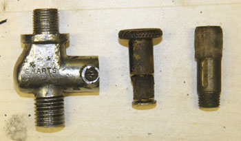
On removing the valves, both cylinders had brand new, unused exhaust valves, I gave all 4 valves a slight grind to clean up the faces and then re-assembled. One of the four spigots for the coolant hoses was badly corroded, the others were OK. I made a new spigot on the lathe and fitted it after having some trouble removing the old one:
I made a saw-cut in the old spigot to allow it to contract and come loose.... |
....then bent one end inwards with the vice - eventually it came out. |
|---|---|
The new spigot is an interference fit - aided by a spot of loctite |
New barrel on left with 3 water holes - old on right with 5. There is a piston ring half way down the new barrel. |
The new cylinder barrels are a later type with only 3 holes for the coolant to circulate around the head. The earlier 5-hole design was prone to head gasket failure apparently. I re-assembled both barrels and cylinder heads and checked that the engine turns over freely. All nuts left loose on the L/H cylinder as the head will have to come off again for re-timing after the flywheel has been off for re-magnetising.
Since writing the above, I have spent a lot of time trying to remove the flywheel. The problem is that thepuller thread on the flywheel hub is badly damaged. So bad in fact that I originally thought it was a tapered thread. The damage wasn't helped by the fact that the club's puller also has quite a worn thread and this made it worse. Eventually, I bought a puller on eBay and spent a lot of time trying with that, but eventually gave up. I'll try it as it is and if the flywheel magnets prove too weak, or if the crankshaft oil seal leaks, I will have to try again.
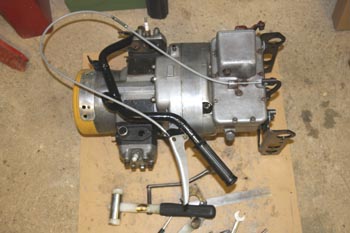
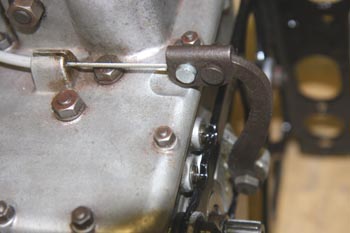
I have now re-assembled the engine, clutch and gearbox. I had a brief panic when I found that the clutch release thrust rods don't protrude from the hole in the back of the gearbox. After consulting with the experts on the LE Velocette forum, I made a temporary thrust rod, which served to prove that the clutch does in fact work (Phew!). I then placed a ball bearing in between the two thrust rods and ground the outer rod down until its length gave correct clutch adjustment. Tested with the new clutch cable and handlebar lever temporarily assembled. The clutch is quite light and disengages nice and cleanly. You will notice on the photo below that the clutch operating lever is tied in position with a piece of string - this advice is given in Technical Notes, no doubt someone learned this trick the hard way!
Clutch cable, etc connected for test |
Close-up of clutch operating lever in correct position |
|---|---|
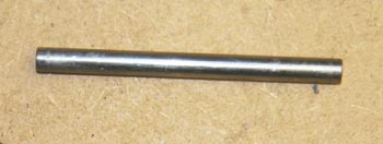
Temporary thrust-rod |
Rear of engine assembly ready for re-fitting. |
Tappets
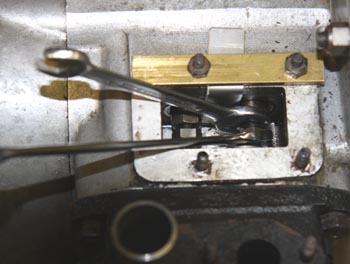
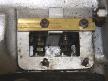
Today it rained, so I decided to get on with some small jobs in the garage. I had a couple of things to finish off around the engine, one of which was adjusting the tappets. This is a fiddly job and best done with the engine out of the bike. The tappets are free to rotate, so to facilitate adjustment, there is a small flat on the top edge, the idea being to insert tool LE 518 as a wedge between the two tappets of one cylinder to prevent them rotating. The tool is easy enough to make from a strip of steel 14.2 mm wide - this needs to be filed to a slight taper on one side over the last inch or so, it's not very critical. The strip is then bent over at right angles so that it can hook over the side of the tappet chamber.
This doesn't work very well in practice because the tool keeps jumping out, so I drilled two holes in a short strip of brass to clamp it in place. See photos:
 |
 |
|---|
Even with the tool in place and behaving itself it isn't very easy because there is very little space in there for two spanners and your fingers! I also found that having adjusted it, when I removed the tool the clearance was wrong again!! By the way, it's 0.004" inlet and 0.006" exhaust. While the tappet covers were off I decided to spruce them up with a fresh coat of paint, they are drying now and can go back on tomorrow.
Petrol Tap
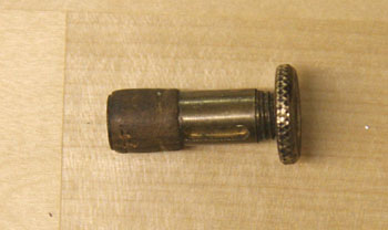
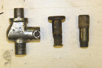
While I was at it, I thought I'd clean and re-assemble the petrol tap using the new cork seal I got from Bullers End. Not so easy, the new seal has a threaded end to take the knob, while the old one has the knob rivetted on:
The good news is that the new seal is a good tight fit, so if I can get the correct knob for it, I'm pretty sure it'll work well.
The petrol Tap (update)
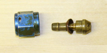
This is worthy of special mention because it is the traditional push-pull variety and uses a cork seal. Needless to say, the cork was completely dried up and useless. I was pleased to find I could get a new plunger with cork from club spares, however when I came to fit this, it was slightly different! See illustrations below. I was able to cut the knob off the old plunger, then drill and tap it to take the rather larger thread of the new plunger. The new plunger thread measured up at 5/16 x 28 tpi, but I threaded the knob at 5/16 x 24 tpi so it would screw on a turn or so and then jam. This worked a treat, but I still put a spot of loctite on as well!
Petrol tap body, old plunger with knob, new plunger |
New plunger with old knob tapped and screwed on. |
|---|
The Petrol Tap (yet again!)
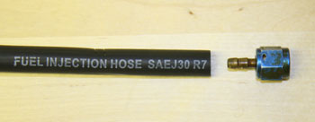
Nice quick job, fit the fuel pipe from the petrol tap to the carb. I had got some nice tubing made from some rubber-looking material (it doesn't smell like rubber) which is certified to BS AU 108 for fuel injection use. It would be ideal, but I think it's too stiff to make the fairly sharp bend from the petrol tap to the carb. Also, I now see that the petrol tap union is not original and doesn't fit too well. It remains to be seen if it'll do because I'll have to get another piece of pipe - I'm tempted to use transparent plastic, I know it'll discolour and go hard, but it'll be a lot easier to fit! I can always replace it every year or so.
The petrol tap union isn't original.... |
....and the pipe is too thick and stiff |
|---|
Transparent petrol pipe bought on eBay and fitted OK.
Starting the engine first time
Well with the fuel pipe fitted, there was no reason not to try to start the engine (even without the front wheel). I filled the sump with oil, checked the ignition timing, took the plugs out and then kicked it over until I could see that oil was filling the filter housing. Quarter filled the tank and turned on the petrol tap. Fuel runs down into the carburetter (showing the value of a transparent pipe!) and no leaks. Choke on, ignition on and kick it over. The engine fires right away but rather weakly and it won't run for more than a few revolutions. Both exhausts are getting hot, so whatever the problem is, it's affecting both cylinders.
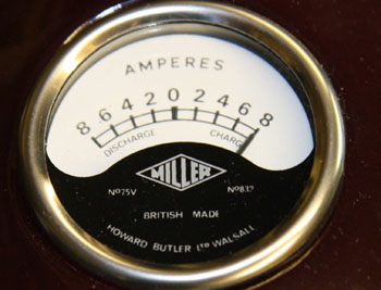
Had a look at the plugs - already getting sooty and they are quite wet. Tried turning the petrol off - after misfiring a few times, it then ran quite well for about 30 seconds until it petered out from lack of fuel. Oil pressure showed about 50psi and the 8-0-8 ammeter went off the scale. This is not a high quality instrument, so I doubt if it is anything like accurate, but the good news is that it seems able to charge at a good rate.
Next job is to strip the carb and sort out the over-rich mixture. I suspect the fuel level is far too high. Unfortunately Amal is closed over Christmas and the New Year, so I shall have to wait until 4th January to see if they have parts in stock.
Now for a confession! I actually started the engine several times by the method of filling the carb and turning off the petrol tap. The first time, the oil pressure gauge read zero. Panic! Going round to the left side of the bike, I saw a huge pool of oil on the floor - I hadn't screwed the pipe union onto the pressure gauge! I have made plenty of mistakes over the months - this was easily the most messy!!
Starting the engine second time
I stripped the carburetter down again and removed the fibre washer from under the needle valve seat. This has the effect of lowering the valve slightly and lowering the petrol level. I have also placed a small aluminium shim on the float to lower it further. The carb must use a plastic (nylon) needle because a brass needle would be too heavy for this small float.
The plastic float needle |
Showing the small aluminium shim on the float |
|---|
On re-assembly, the engine started very easily (first kick) and runs well, though I think it still sounds a bit rich and the plugs are a bit sooty. It seems to misfire slightly at higher revs, but this will be difficult to judge very well until I am able to ride it.
The oil pressure is good and I am pleased with the charging - it still manages to charge at 4 Amps or so even with the headlamp on.
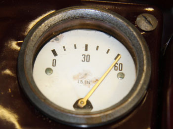
Oil pressure warm at about 2500 rpm |
Charge rate at 2500 rpm, lights off, battery half charged. |
|---|
I wouldn't be too sure about the accuracy of either of these instruments - the oil pressure gauge moves in steps and the ammeter is a cheap modern replica. All the same, the signs are good!
Carburetter (again)
Spoke to Amal. They are about to release a repair kit for the 363 carb, should be ready by the end of January. In the meantime I ordered a No 15 pilot jet and a new banjo of the correct type.
Carburetter Update
The Amal service kit is now available but it only contains a limited number of parts. Most useful of these are the float needle and a number of fibre washers. The new float needle is aluminium, with a "viton" tip. Unfortunately the float itself is not available - mine is somewhat dented and a bit tired. The kit also contains a new throttle needle as well as a pilot air screw and spring. I fitted the new parts and it does seem to work somewhat better, though the new float needle does seem to have a slight tendency to stick - sometimes leading to starvation and sometimes flooding! I'm not entirely happy with the carburetter.
Updated: 23rd July 2011